Transducers
July 9th 2018
A couple of months ago met Augusto Weber in the FabLab. He was looking for someone who could help him with his PhD research. "Effects of Music in Combination with Vibration in Acupuncture Points on the Treatment of Fibromyalgia".
He told me a little about his topic and that he needed help with the electronic aspect of his research.
Since I am also very interested in topics such as music, technology applied to Science, Chinese Medicine, I decided to help him in this endeavour.
Step number one is to reconstruct the transducers done for his frequency generator machine. And this is what I'll mainly cover in this page.
== A transducer is a device that converts energy from one form to another. Usually a transducer converts a signal in one form of energy to a signal in another. ==
Where to start?
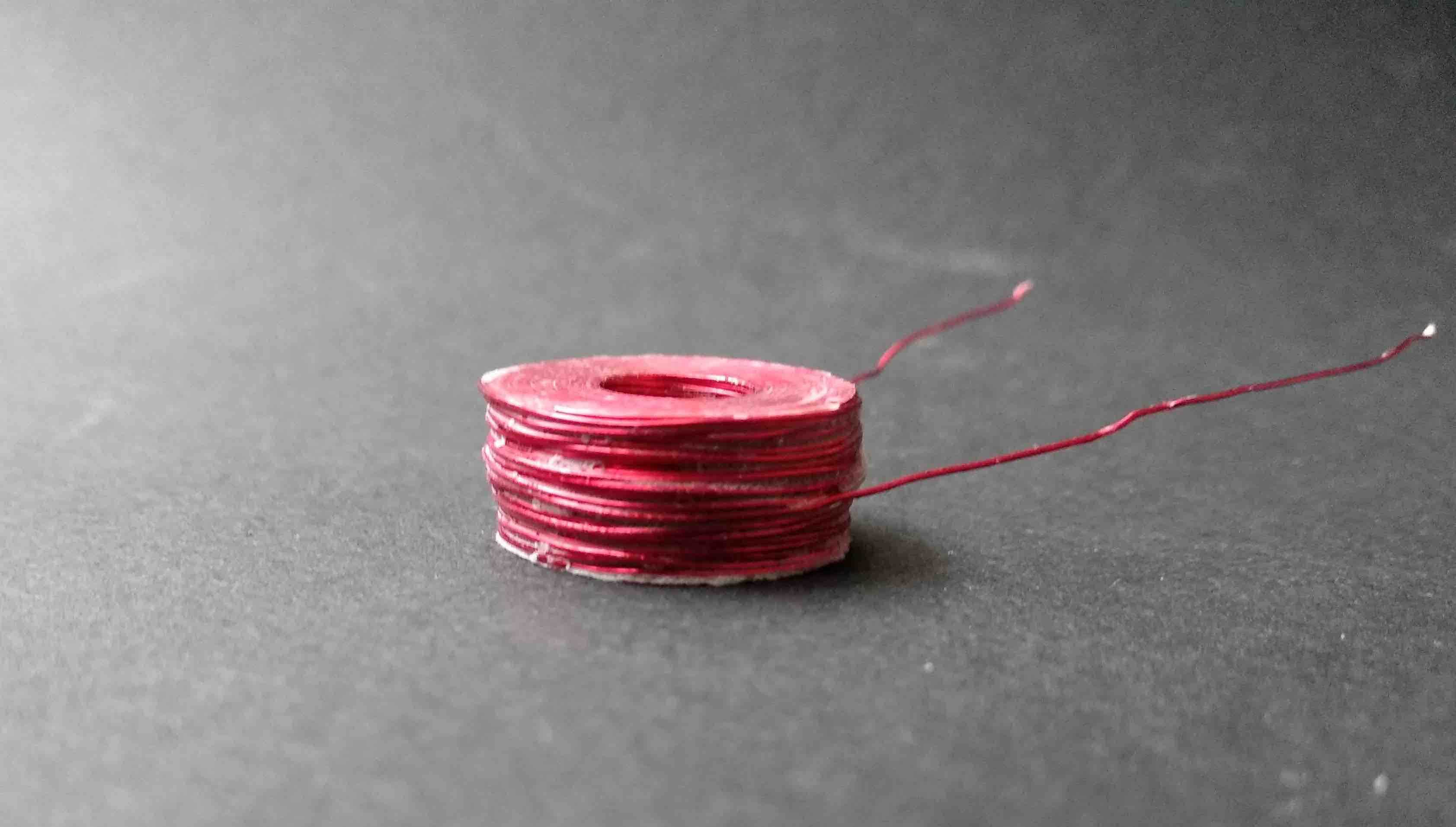
After some research and having in mind Niel's encouraging words to make coils/Solenoinds ourselves, I came up with a plan. Well, a coil is basically a wire in a loop. The current passing the loop generates a magnetic field perpendicular to the direction of the current. See Right Hand Palm Rule. I would then 3D print a structure to contain the insulated copper wire and leave a slit for the magnet in the structure's core. The idea is that, once current starts to oscillate through the copper wire, the magnetic field generated will carry the magnet, generating the desired vibrations.
The first result:
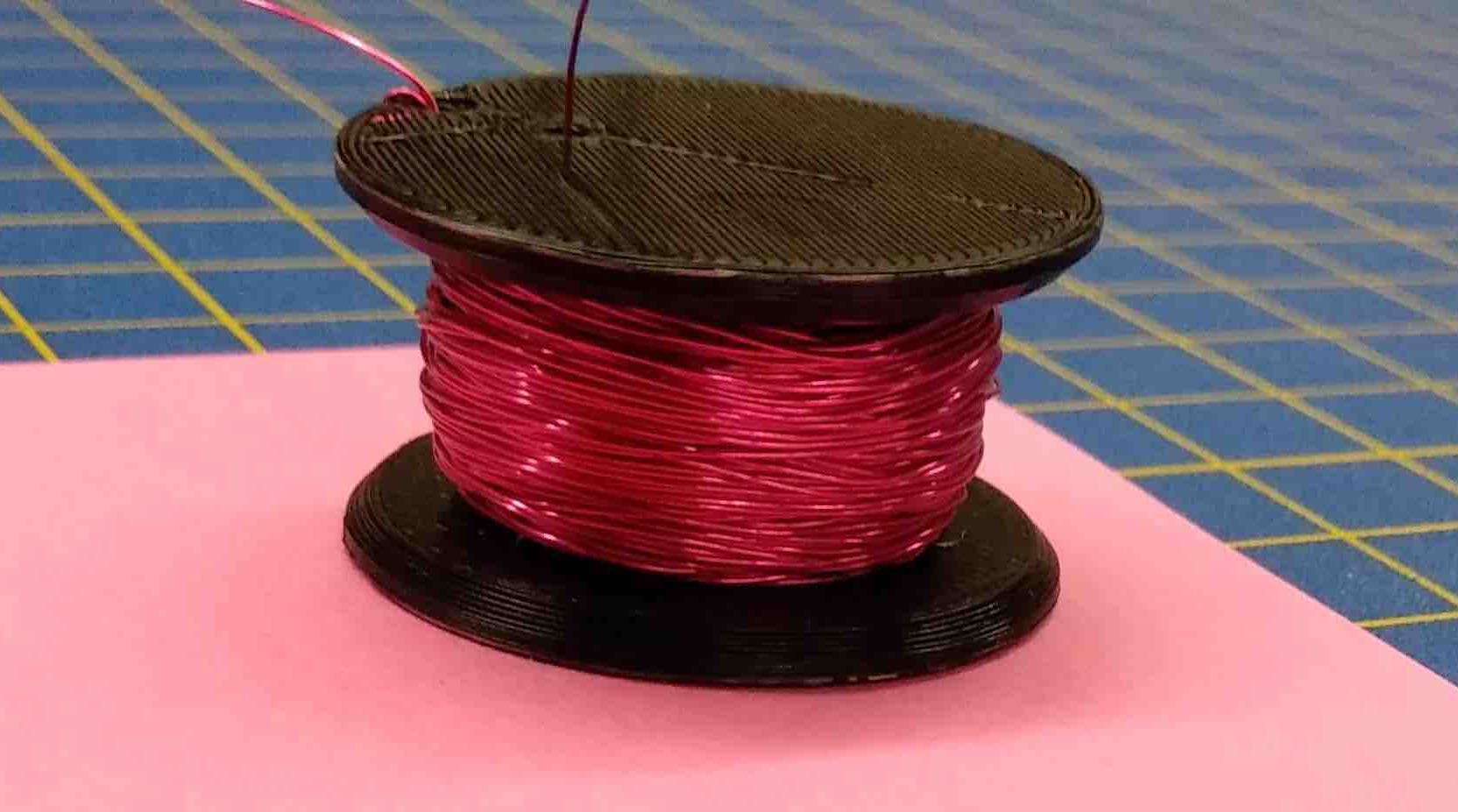
Not bad, right?!
And ==this is how I coiled it:==
Update!!
-IMU // 3D accelerometer and 3D gyroscope
This sensor just got to my favorite's list. Simply because of the amount of projects you can integrate this sensor to.
This one specifically is the AltIMU-10 v5, from Polulu.
Here is its datasheet and its Arduino's Library.
You've probably seen Camera gimbal stabilizers. They use these tiny devices:
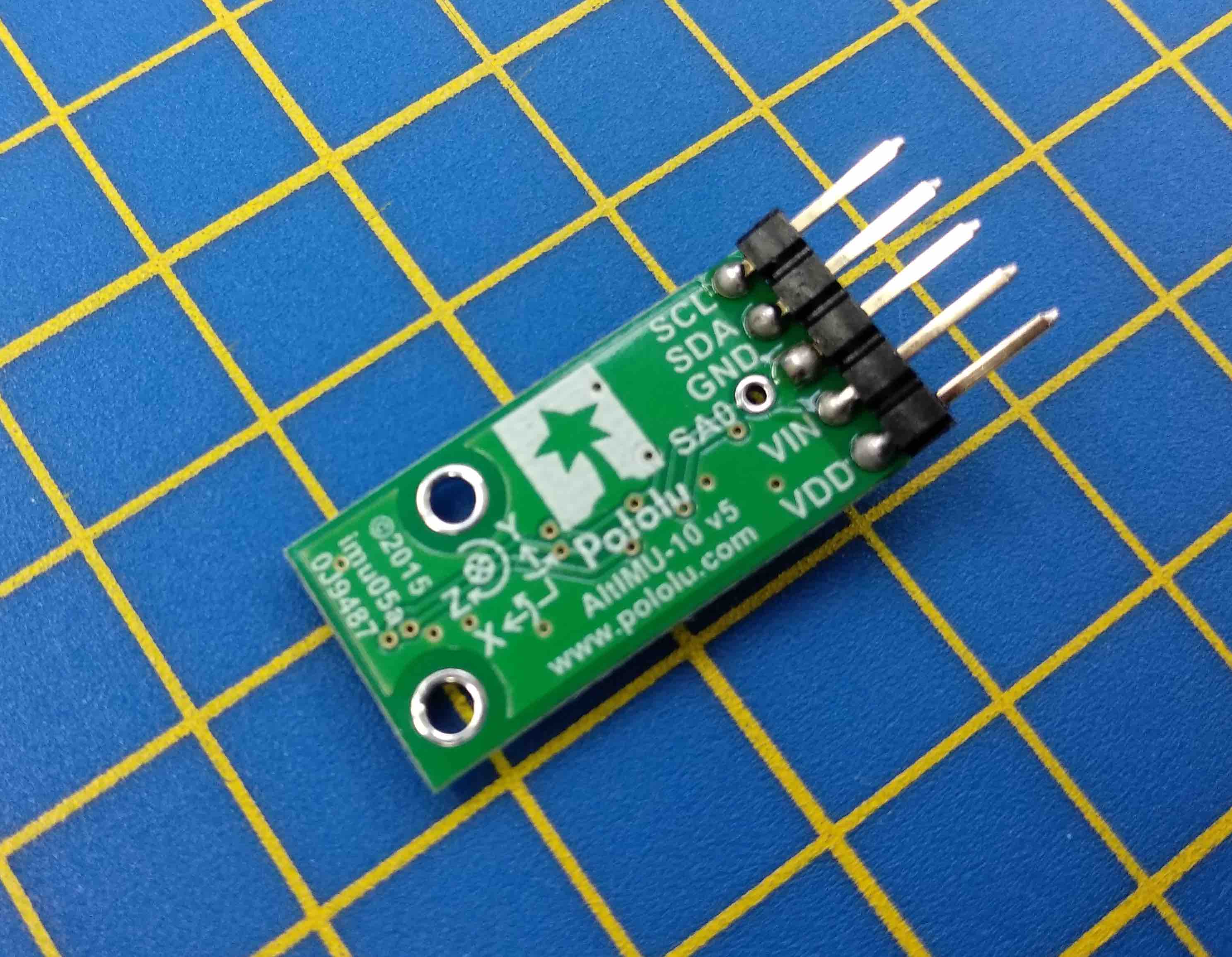
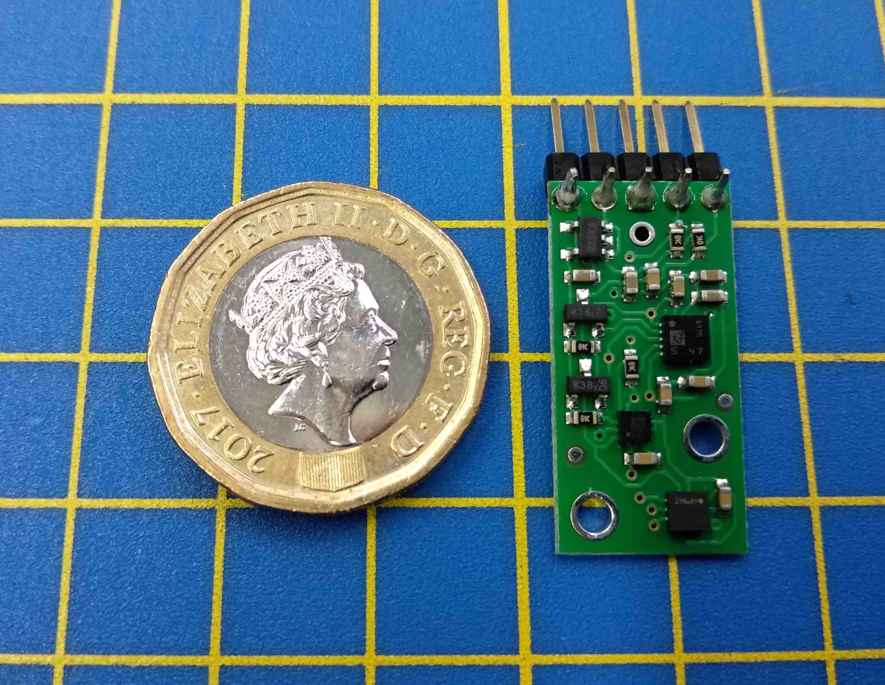
AltIMU-10 v5 component at Polulu's website.
Wiring
Wiring the Imu is fairly straight-forward:
5V Arduino boards: (This one I used for the Bueno Board) (including Arduino Uno, Leonardo, Mega; Pololu A-Star 32U4)
Arduino   LSM6 board
-------   ----------
     5V - VIN
    GND - GND
    SDA - SDA
    SCL - SCL
3.3V Arduino boards:
(including Arduino Due)
Arduino   LSM6 board
-------   ----------
    3V3 - VIN
    GND - GND
    SDA - SDA
    SCL - SCL
Code
I'm helping Sophie with her final project and we're combining RGB LEDs with these IMU modules.
She'll have one on each arm and she'll dance hip-hop (She rocks the dance floor. Yes, spoiling a bit).
So far we got this far with the code:
/*

The sensor outputs provided by the library are the raw

16-bit values obtained by concatenating the 8-bit high and

low accelerometer and gyro data registers. They can be

converted to units of g and dps (degrees per second) using

the conversion factors specified in the datasheet for your

particular device and full scale setting (gain).


Example: An LSM6DS33 gives an accelerometer Z axis reading

of 16276 with its default full scale setting of +/- 2 g. The

LA_So specification in the LSM6DS33 datasheet (page 11)

states a conversion factor of 0.061 mg/LSB (least

significant bit) at this FS setting, so the raw reading of

16276 corresponds to 16276 * 0.061 = 992.8 mg = 0.9928 g.

*/


#include <Wire.h>
#include <LSM6.h>

int ledR = 3;           // the PWM pin the LED is attached to
int ledG = 5;           // the PWM pin the LED is attached to
int ledB = 6;           // the PWM pin the LED is attached to

LSM6 imu;

char report[80];


void setup()

  pinMode(ledR, OUTPUT);
  pinMode(ledG, OUTPUT);
  pinMode(ledB, OUTPUT);

  Serial.begin(9600);

  Wire.begin();

  if (!imu.init())

  {

    Serial.println("Failed to detect and initialize IMU!");

    while (1);
  }

  imu.enableDefault();
}


void loop()

{

  imu.read();

// This was on the original example "Serial" from the LSM6 Library:

/*snprintf(report, sizeof(report), "A: %6d %6d %6d    G: %6d %6d %6d",

    imu.a.x, imu.a.y, imu.a.z,

    imu.g.x, imu.g.y, imu.g.z);

   Serial.println(report);

*/


int gyroX = imu.a.x;
int gyroY = imu.a.y;
int gyroZ = imu.a.z;

//Remapping the results from the IMU to 8bits RGB LEDs:
gyroX = map(gyroX, -20000, 20000, 0, 255);
gyroY = map(gyroY, -20000, 20000, 0, 255);
gyroZ = map(gyroZ, -20000, 20000, 0, 255);


Serial.print("GyroX:");
Serial.println(gyroX);

Serial.print("GyroY:");
Serial.println(gyroY);

Serial.print("GyroZ:");
Serial.println(gyroZ);


  // set the brightness of pin 3, 5, 6:

  analogWrite(ledR, gyroX);
   analogWrite(ledG, gyroY);
    analogWrite(ledB, gyroZ);


//To be maybe considered:
 // change the brightness for next time through the loop:
//  brightness = brightness + fadeAmount;


//To be maybe also considered:
/* reverse the direction of the fading at the ends of the fade:
if (brightness <= 0 || brightness >= 255) {
fadeAmount = -fadeAmount; }
wait for 30 milliseconds to see the dimming effect
delay(30);
*/


  delay(100);

}
Using as well an IMU, these guys did something Very cool!