BEAVER CNC
On the Eagle board above, note the map of parts.
Downloadable files for BEAVER CNC <<-- Here
Marlin for Ramps 1.4
Lines changed or consider changing in the Configuration.H file:
77: #define STRING_CONFIG_H_AUTHOR "(BeaverCNC Team 10/May/2018)"// Who made changes when.
122: #define MOTHERBOARD BOARD_RAMPS_14_EFB // Where we declared Ramps1.4 as the Mother Board we're using
127: #define CUSTOM_MACHINE_NAME "Beaver CNC" // Naming the machine
137: #define EXTRUDERS 1 // no extruders but use the E command in G code to control direction of the Nibbler
289: #define TEMP_SENSOR_0 1 // add later thermistor to control temp on the tip of the nibbler's head - Also had to have this to one. Zero failed to compile.
341: //#define PIDTEMP // uncomment this to enable PID. Do it if a a nozzle is installed
342: #define BANG_MAX 0     // Limits current to nozzle while in bang-bang mode; 255=full current; I set it to 0 to limit current to nozzle, since we havnt got one
394: #define MAX_BED_POWER 0 // limits duty cycle to bed; 255=full current; I set to zero
421: //#define PREVENT_COLD_EXTRUSION // Uncomment when adding hot-end
422: //#define EXTRUDE_MINTEMP 0 // was 170

//Endstops:
475: //#define USE_ZMIN_PLUG // UnCommented it since no working - Had to have this on. Why? Maybe add a jump wire to have Z end stop always on
476: #define USE_XMAX_PLUG // I Uncommented it to include xmax endstop
477: #define USE_YMAX_PLUG // I Uncommented it to include ymax endstop
//End-Stops:
495: #define X_MIN_ENDSTOP_INVERTING true // set to true to invert the logic of the endstop. I changed this to True. Pushed Endstop was reading Open.
496: #define Y_MIN_ENDSTOP_INVERTING true // set to true to invert the logic of the endstop. I changed this to True. Pushed Endstop was reading Open.

498: #define X_MAX_ENDSTOP_INVERTING true // set to true to invert the logic of the endstop.
499: #define Y_MAX_ENDSTOP_INVERTING true // set to true to invert the logic of the endstop.

 -Compare these (till 559) below with the next table "feeds and speeds"
532: #define DEFAULT_AXIS_STEPS_PER_UNIT   { 200, 75, 4000, 80 } // x was 80 and was driving 40mm when told to drive 100mm on software
//    y was 80 as well, was driving 107mm Real when sending 100mm

539: #define DEFAULT_MAX_FEEDRATE          { 500, 500, 5, 500 }
547: #define DEFAULT_MAX_ACCELERATION      { 800, 800, 100, 800 }
557: #define DEFAULT_ACCELERATION          300    // X, Y, Z and E acceleration for printing moves
558: #define DEFAULT_RETRACT_ACCELERATION  300    // E acceleration for retracts
559: #define DEFAULT_TRAVEL_ACCELERATION   300    // X, Y, Z acceleration for travel (non printing) moves
569: #define DEFAULT_XJERK                 5.0 // was 5
570: #define DEFAULT_YJERK                 5.0 // was 5

751: #define INVERT_X_DIR true // inverted DIR was needed
752: #define INVERT_Y_DIR true // Keep that in mind if invert DIR needed
753: #define INVERT_Z_DIR false // Keep that in mind if invert DIR needed
760: // For direct drive extruder v9 set to true, geared extruder set false.
761: #define INVERT_E0_DIR false // For the E motor for the Nibbler's rotation
774: // Direction of endstops when homing; 1=MAX, -1=MIN // If needed
774: // :[-1,1]
776: #define X_HOME_DIR -1
777: #define Y_HOME_DIR -1

1109: // EEPROM
//
// The microcontroller can store settings in the EEPROM, e.g. max velocity...
// M500 - stores parameters in EEPROM
// M501 - reads parameters from EEPROM (if you need reset them after you changed them temporarily).
// M502 - reverts to the default "factory settings".  You still need to store them in EEPROM afterwards if you want to.
This is a table we should keep in mind when trimming Feeds and Speeds:
Starts at line 507 of Configuration.H of Marlin Firmware (Open with Arduino IDE)
//=============================================================================
//============================== Movement Settings ============================
//=============================================================================
// @section motion

/**
 * Default Settings
 *
 * These settings can be reset by M502
 *
 * Note that if EEPROM is enabled, saved values will override these.
 */

/**
 * With this option each E stepper can have its own factors for the
 * following movement settings. If fewer factors are given than the
 * total number of extruders, the last value applies to the rest.
 */
//#define DISTINCT_E_FACTORS

/**
 * Default Axis Steps Per Unit (steps/mm)
 * Override with M92
 *                                      X, Y, Z, E0 [, E1[, E2[, E3[, E4]]]]
 */
#define DEFAULT_AXIS_STEPS_PER_UNIT   { 80, 80, 4000, 500 }

/**
 * Default Max Feed Rate (mm/s)
 * Override with M203
 *                                      X, Y, Z, E0 [, E1[, E2[, E3[, E4]]]]
 */
#define DEFAULT_MAX_TE          { 300, 300, 5, 25 }

/**
 * Default Max Acceleration (change/s) change = mm/s
 * (Maximum start speed for accelerated moves)
 * Override with M201
 *                                      X, Y, Z, E0 [, E1[, E2[, E3[, E4]]]]
 */
#define DEFAULT_MAX_ACCELERATION      { 3000, 3000, 100, 10000 }

/**
 * Default Acceleration (change/s) change = mm/s
 * Override with M204
 *
 *   M204 P    Acceleration
 *   M204 R    Retract Acceleration
 *   M204 T    Travel Acceleration
 */
#define DEFAULT_ACCELERATION          3000    // X, Y, Z and E acceleration for printing moves
#define DEFAULT_RETRACT_ACCELERATION  3000    // E acceleration for retracts
#define DEFAULT_TRAVEL_ACCELERATION   3000    // X, Y, Z acceleration for travel (non printing) moves

/**
 * Default Jerk (mm/s)
 * Override with M205 X Y Z E
 *
 * "Jerk" specifies the minimum speed change that requires acceleration.
 * When changing speed and direction, if the difference is less than the
 * value set here, it may happen instantaneously.
 */
#define DEFAULT_XJERK                 10.0
#define DEFAULT_YJERK                 10.0
#define DEFAULT_ZJERK                  0.3
#define DEFAULT_EJERK                  5.0
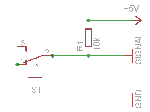
The reason there are 3 pins for Endstops is for a pullup resistor.
I hacked a Pullup system using a SMD 10k Ohms Res, soldered it from the VCC pin to the
Signal pin, and GND in the middle:
|VCC|GND|SIGNAL|
Good link for Ramps wiring also:
https://www.drdflo.com/food-printer-frame/
http://reprap.org/wiki/File:Rampswire14.svg
http://reprap.org/wiki/RAMPS_1.4
http://doc.3dmodularsystems.com/electronic-wiring/
What to do with it:
Metal Etching