Bueno Electronics:
Bueno Board V2 - Current Version - 15th April 2018
- [x] Started
- [x] On-Going
- [x] Fully-Functional
- [x] Open-Source
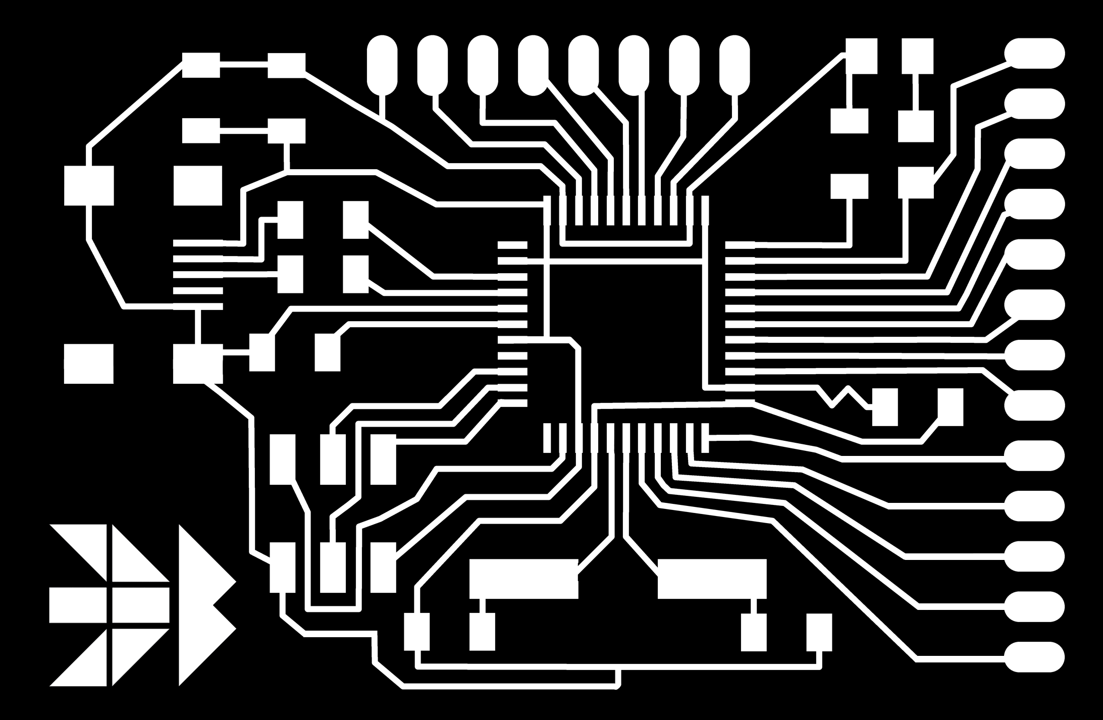
Bueno Board - V2 || Eagle Files and PNGs <<-- Click here
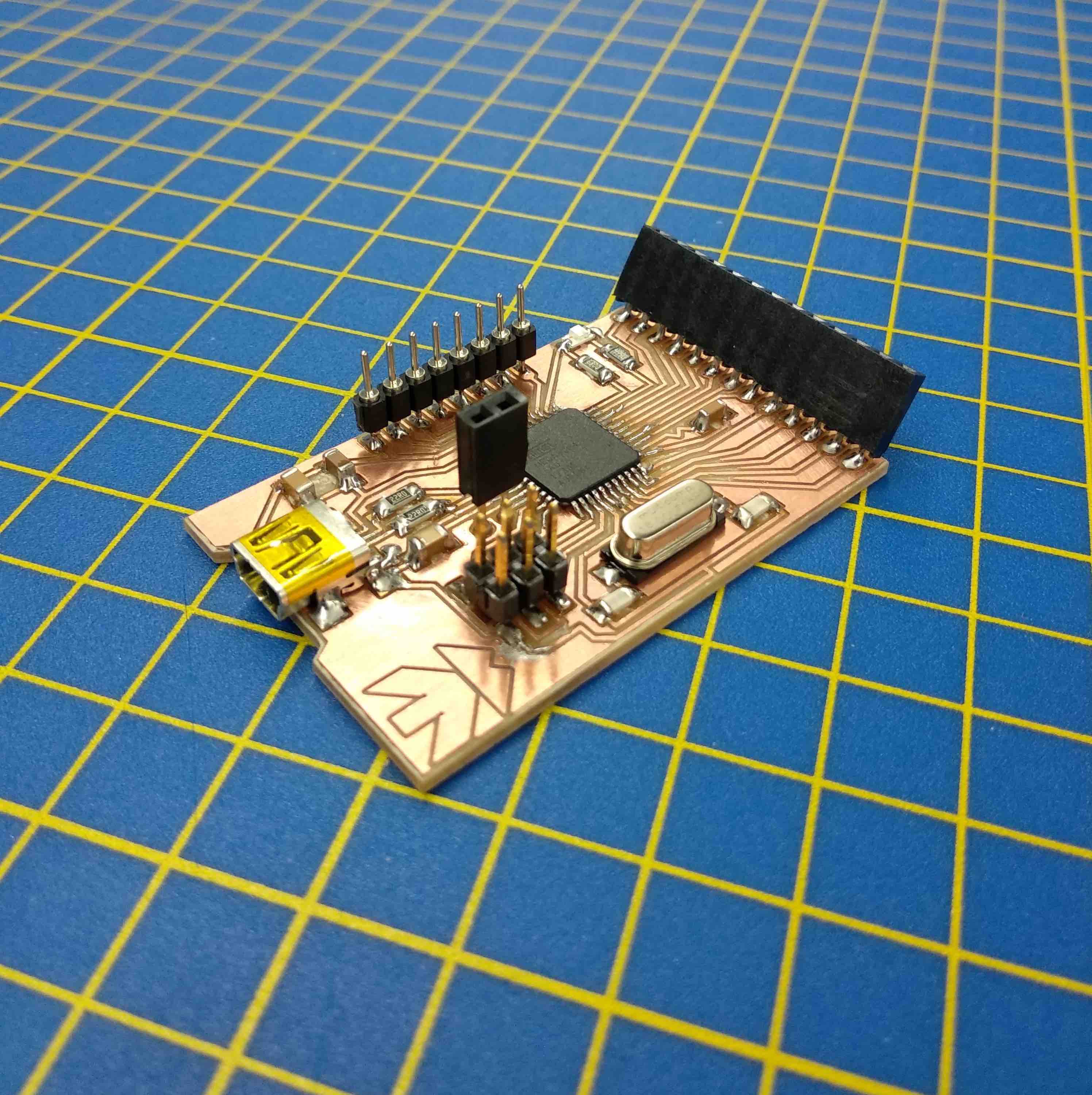
Looks like a space-ship. Almost actually. Electricity travel at +/- 90% Light-Speed.
Fast enough to travel around Earth in about 18 seconds.
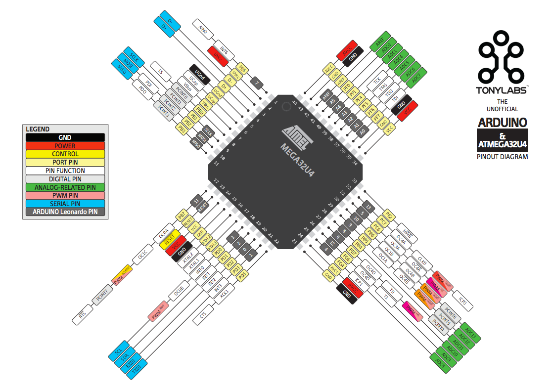
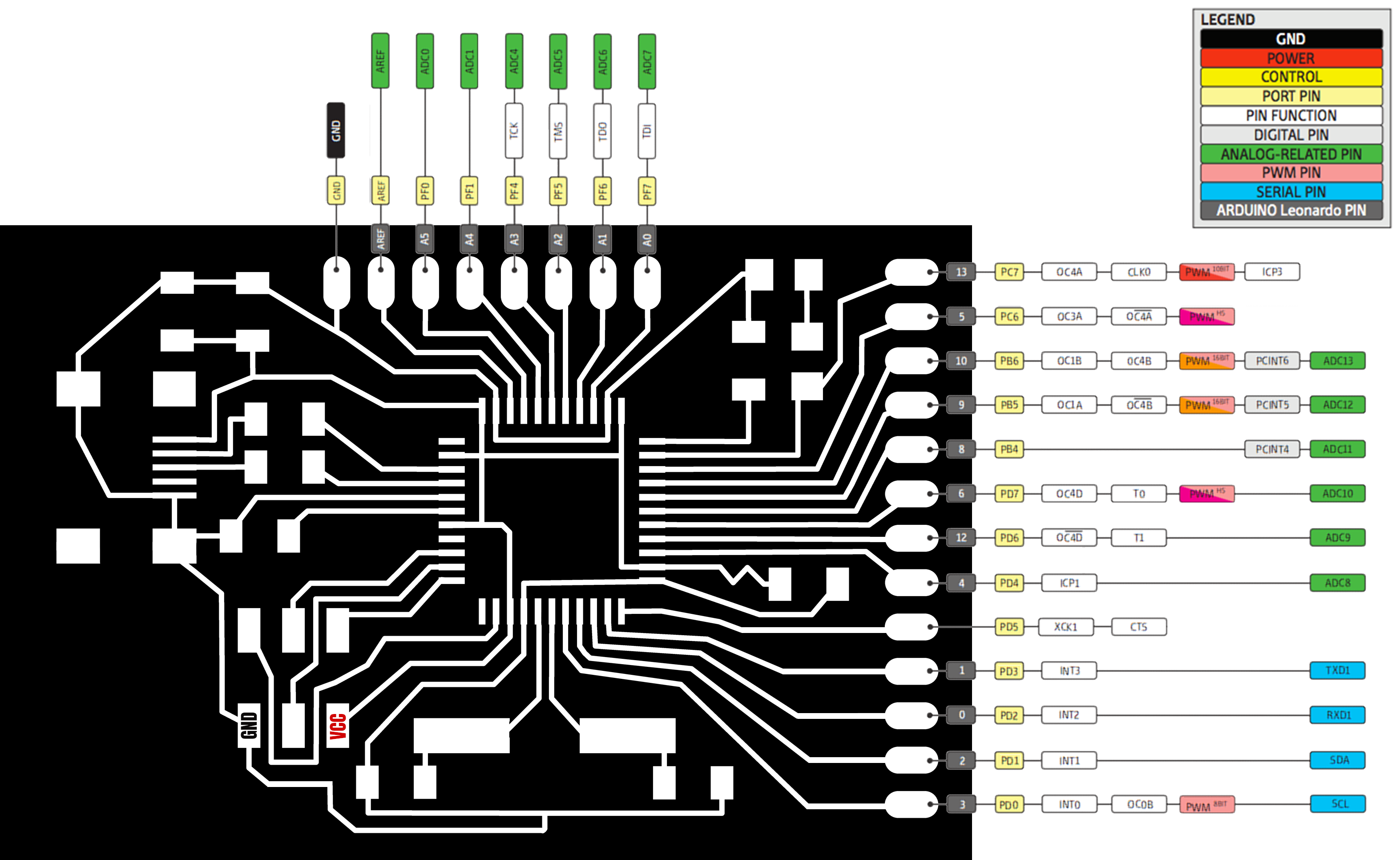
Daniele Ingrassia suggested a Pinout Map of the board. There you go (above). It comes in handy, indeed. Thank you!
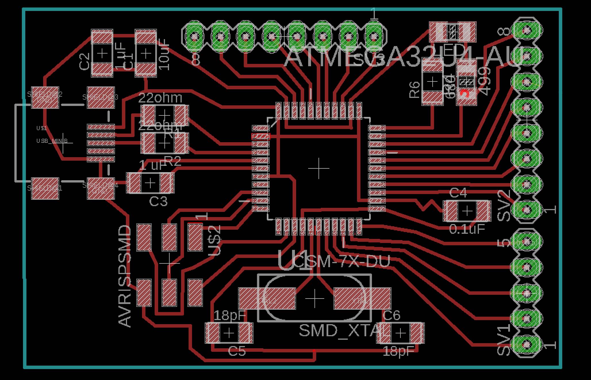
BOM (Bill of Material) - Bueno Board V2
-C1 10 uF CAP US1206FAB - Recommended for VBUS line
-C2 1 uF CAP US1206FAB
-C3 1 uF CAP US1206FAB - Ucap
-C4 0.1 uF CAP US1206FAB - Coringa
-C5 18 pF CAP US1206FAB - Crystal
-C6 18pF CAP US1206FAB - Crystal
-R1 22ohm RES D- US1206 - USB data
-R2 22ohm RES D+ US1206 - USB data
-R4 499 RES US1206 - LED
-R6 680 RES US1206 - PE2 (PORT E bit 2) - Hardware bootloader activation Page 81
-LED Size 1206 (3216 metric)
-SV1 5x1 PIN HEADER - Female or Male, your choice
-SV2 8x1 PIN HEADER - Female or Male, your choice
-U$1 USB MINI-B
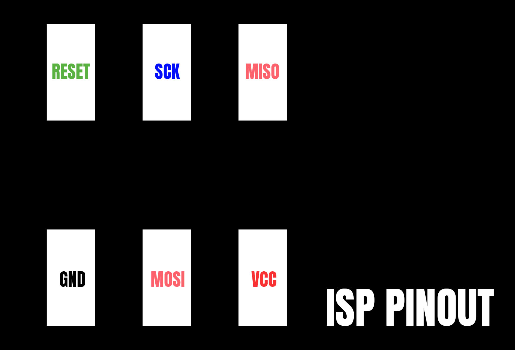
-U$2 AVRISPSMD - In-Circuit System Programming Surface Mount Pin Header 2x3
-U$3 16.000 Hz CRYSTAL - SMD - CSM-7X-DU
-U1 ATMEGA32U4-AU ATMEGA32U4-AU QFP80P1200X1200X120-44N 8-bit Microcontroller
with ISP Flash and USB Controller
BEGINNINGS
On my Input Device's Week of my Fab-Academy 2016 [Barcelona] was when I first created it. There you see the 1st version of the board. I initially called it Luiz-ino. Does not look good, I warn you. And this is the beauty of it. The ability to improve. The 1st evolution of it, the Jalap-ino, turned out better.
Great Ferdi Meier my instructor and guru, suggested me to try the ATMEGA32u4, said the past couple years no F.A. student in that lab managed to produce a board with it. Challenge accepted. (I mentioned him I wanted a board with USB instead of FTDI)
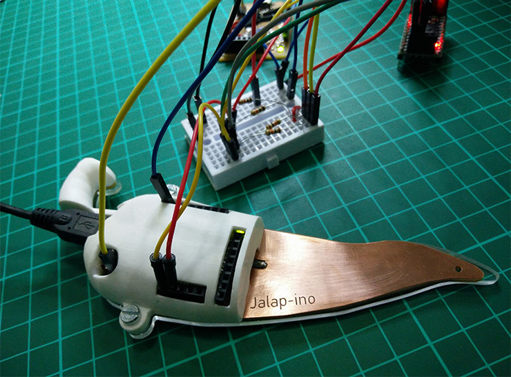
In molding and casting, I gave Jalap-ino a shell (here), like you do it to cars. This board above has this copper tip, that's a Step-Response (With 1Mega_Ohm Res), aka Capacitive Sensing. To my next iteration of the Jalap, I'll add a capacitor to the Step Response sensor, for noise filtering, suggested here. You can program it to measure soil humidity. I used it as a touch button. Click and double click.
RELEVANT FINDINGS
While re-designing the board this time, I spent a good time reading its datasheet. I've found the right values for the decoupling capacitors, the exact resistor values for USB Data Upstreams, understood better some important pins, and while at it, learned many other things, yak shaving. -(Tks Kelly)
- PIN PE2 - Port E bit 2
From the datasheet:
Port E (PE6,PE2) Port E is an 8-bit bi-directional I/O port with internal pull-up resistors (selected for each bit). The Port E output
buffers have symmetrical drive characteristics with both high sink and source capability. "As inputs, Port E pins that are externally pulled low will source current if the pull-up resistors are activated"
The Port E pins are tristated when a reset condition becomes active, even if the clock is not running.
I'm using a 680 Ohms Resistor connecting the PE2 to GND. This works. I am researching about it to better understand how to best use these ports PE2 and PE6.
- D+ and D- (USB Data Upstream Port):
2.2.8 D-
USB Full speed / Low Speed Negative Data Upstream Port. Should be connected to the USB D- connector pin with a serial 22Ohm resistor.
2.2.9 D+
USB Full speed / Low Speed Positive Data Upstream Port. Should be connected to the USB D+ connector pin
with a serial 22Ohm resistor.
This explained why we need these 22 Ohms Resistors connected from the USB to the D- and D+ pins of the ATMEGA32U4.
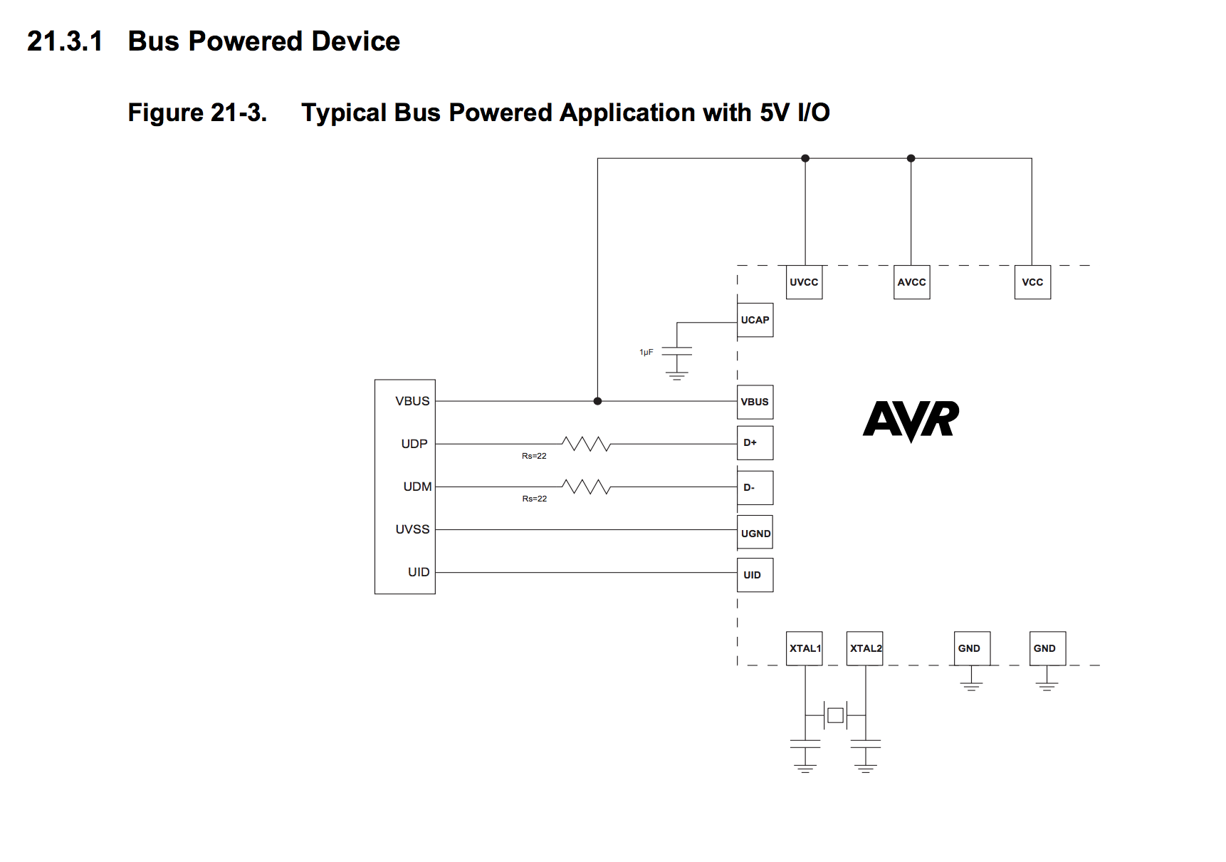
- 21.5 Design Guidelines (Datasheet page 259)
-Serial resistors on USB Data lines must have 22 Ohms value (±5%)
-Traces from the input USB receptable (or from the cable connection in the case of a tethered device) to the USB microcontroller pads should be as short as possible, and follow differential traces routing rules
(same length, as near as possible, avoid via accumulation)
-Voltage transient /ESD suppressors may also be used to prevent USB pads to be damaged by external disturbances
-Ucap capacitor should be 1µF (±10%) for correct operation
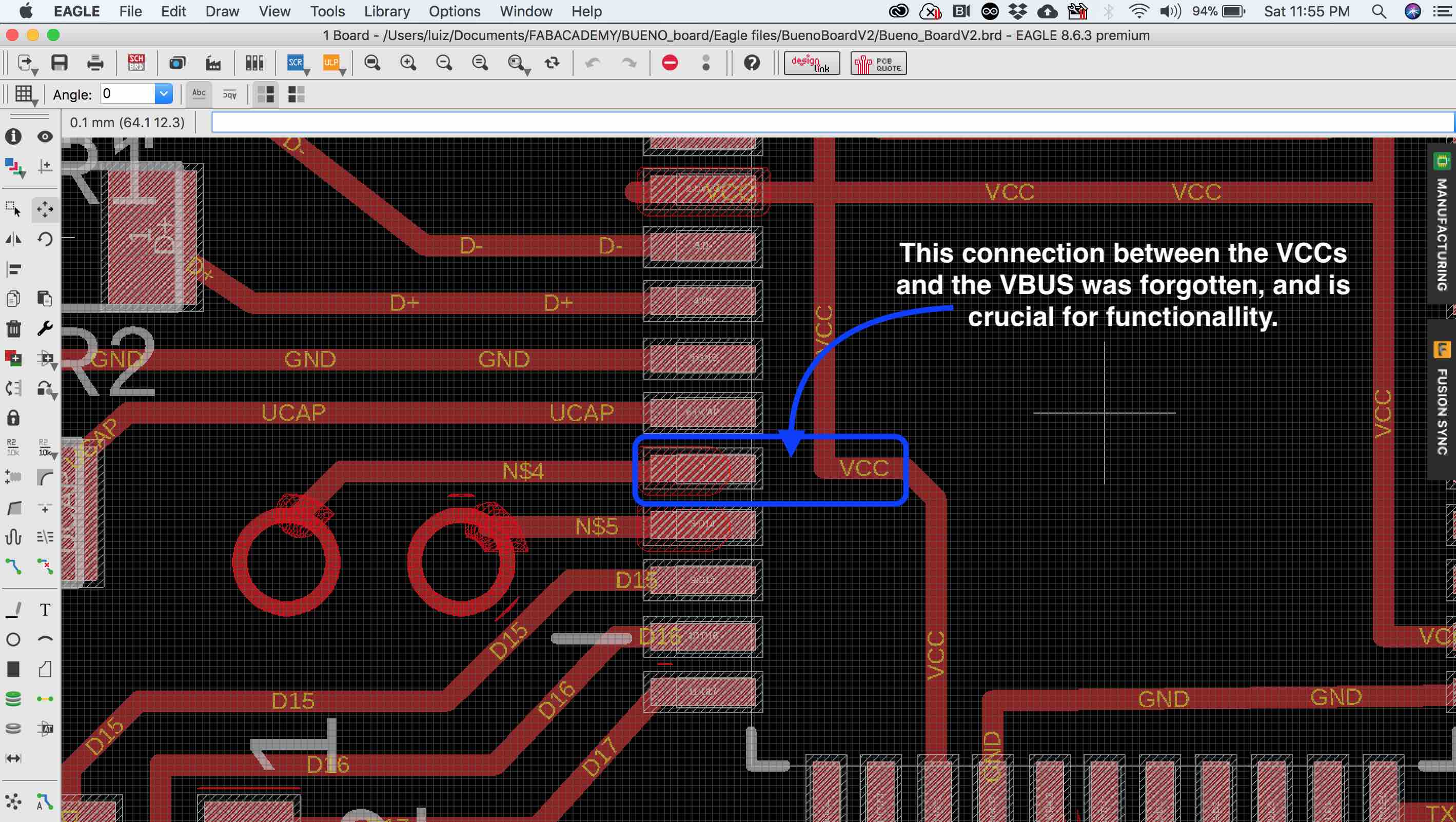
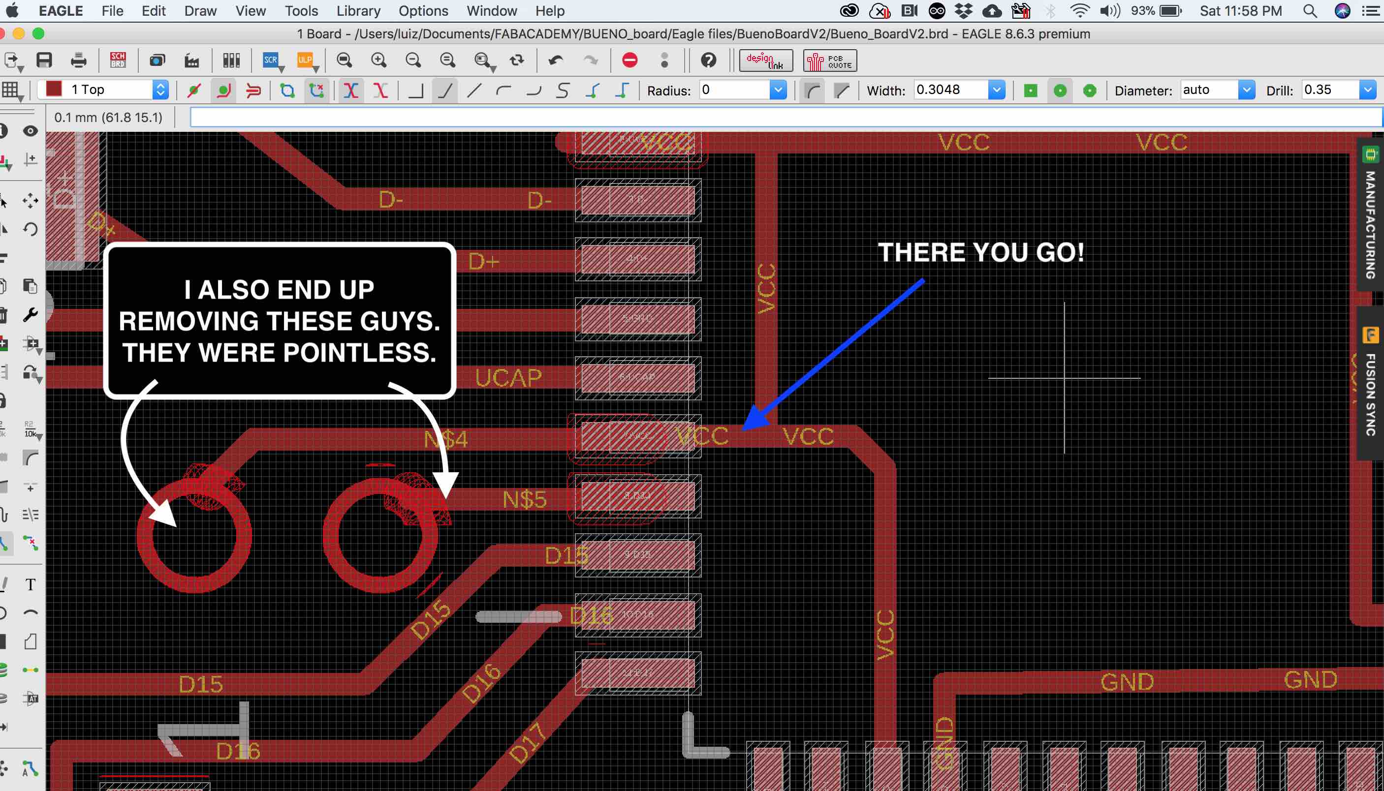
-A 10µF capacitor is highly recommended on VBUS line.
Found here many answers I was looking for. The 10uF Capacitor for the VBUS, the 1uF for the Ucap, the 22 Ohms resistor for the USB data lines...
I also found this very* helpful:
Bypass Cap:
One of my students, Andrew Sleigh asked me about the Bypass capacitors. Why two of the capacitors are wired together in one power-rail, the C1(10uF) and C2(1uF)? The question to use in your search engine is: "Why to use bypass capacitors?"
EEVblog on his "Bypass Capacitor Tutorial" answers this question by saying that, using different Capacitors of different values will lower the overall impedance, in a Impedance x Frequency graphic. Giving you better performance in therms of EMI and Decoupling.
An inductor will resist change in current. Therefore impedance is unwelcomed in many locations in your Microcontrolling board. If suddenly your microchip triggers a switch, inductunce will "fight" against it.
"No further Changes!" - Unknown Inductor
THE PROCESS
-Design
Designing the board seemed easy since I was iterating the Bueno Board V1 which works.
The thing about improvements is that you're starting from the point you gave up when you last did it.
I did have fun, though.
Reading the datasheet is summing up a lot of what I did.
Here are some images of it:
Using Golden Ratio, I created a new Width x Height proportion to the board, now with 6 capacitors less, the board became slightly smaller.
Not sure yet, perhaps I prefer the old proportion, though.
I'll soon add an image with them side by side.
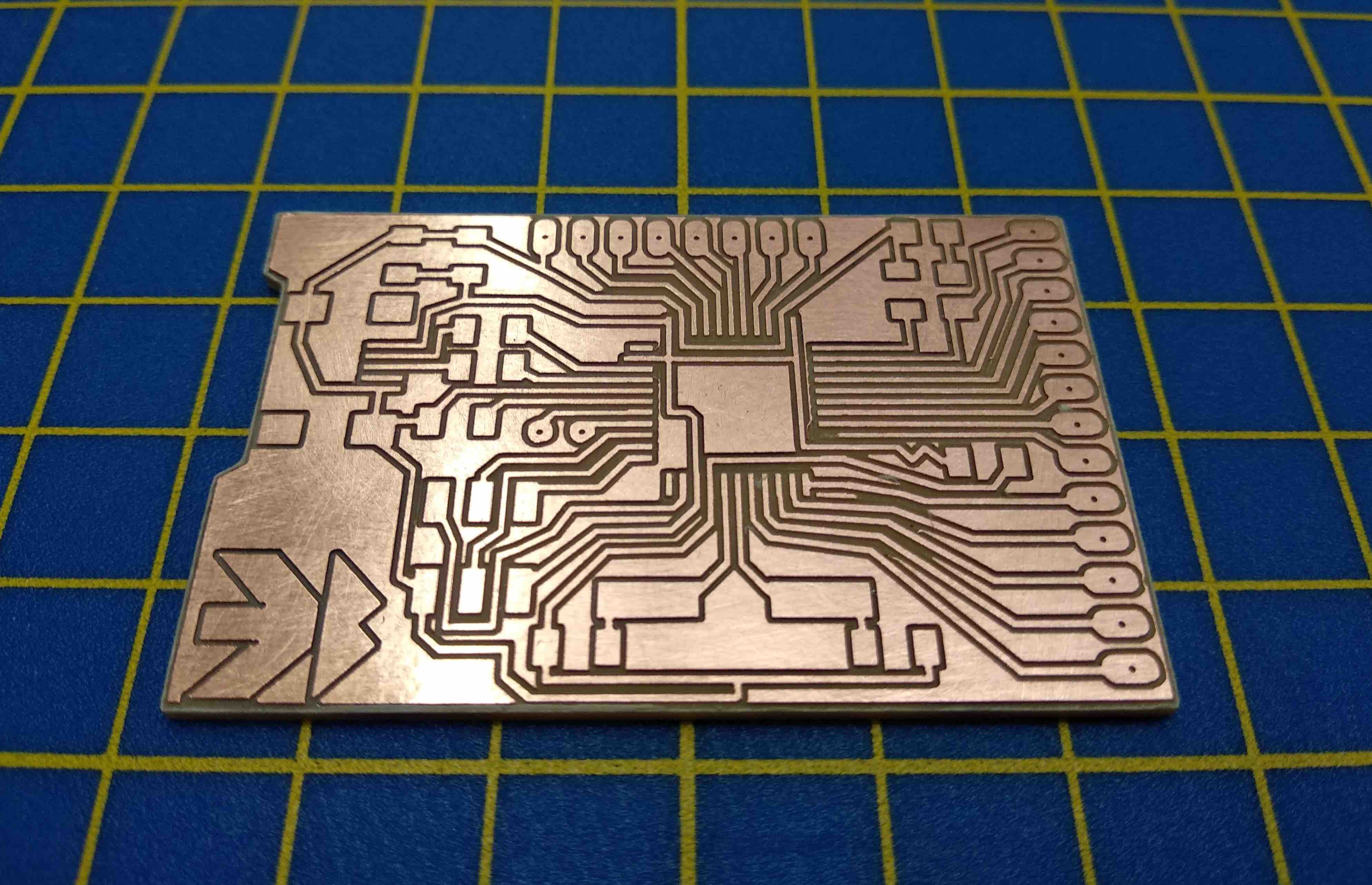
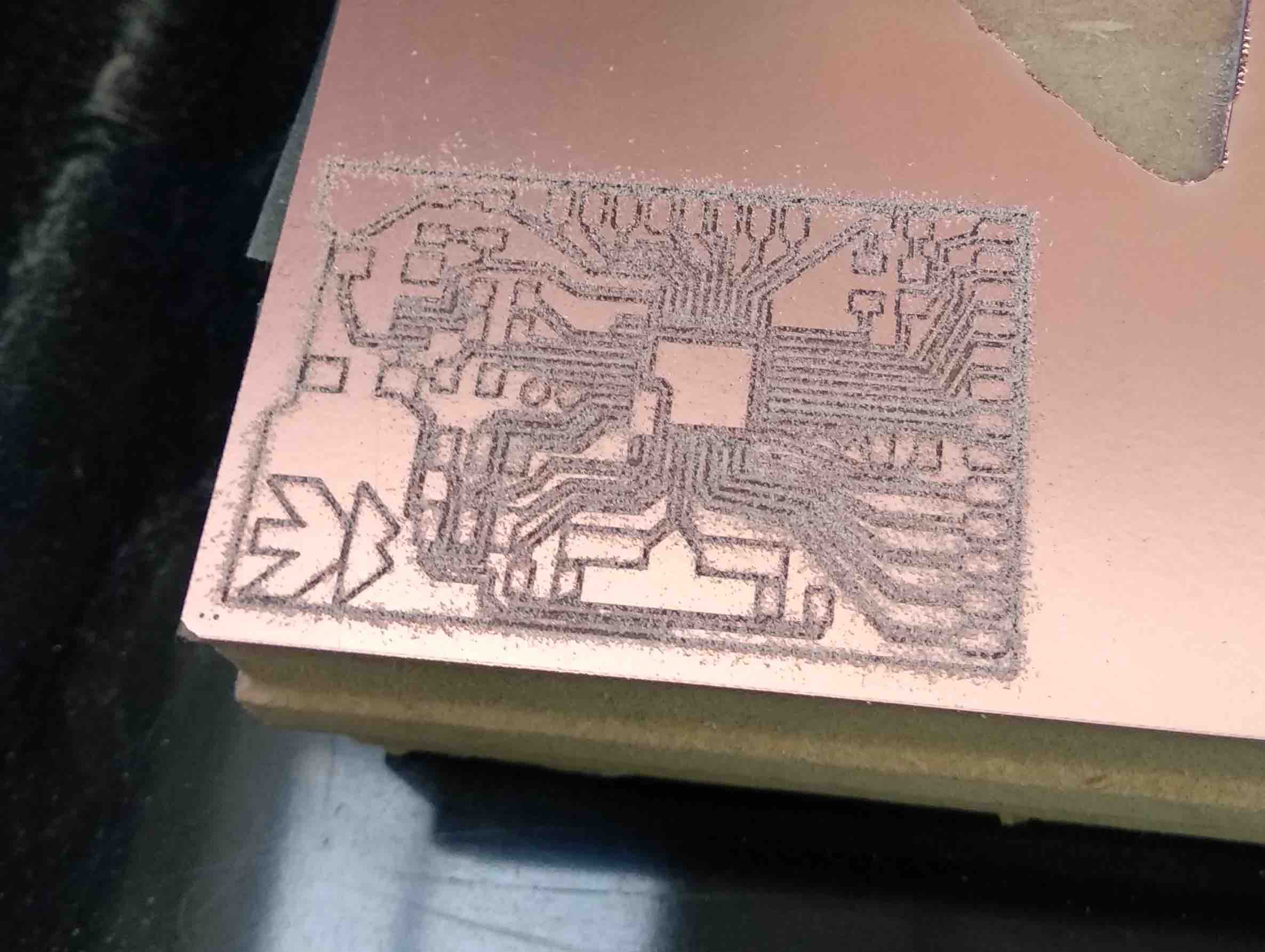
Milling
Having a ROLAND MDX50 takes milling to another level. Equipped with tool exchanging, you tell your software to take another tool and it does it on the fly, mid milling it stops, exchange tools, zero "Z" axis with the new tool, and goes back milling.
Tool exchanging doesn't work with fabmodules.org, you must select the desired tool prior milling.
[FabAcademy Brighton 2018 students] (http://fab.academany.org/2018/labs/fablabbrighton/) did a great job documenting it, here.
Testing
Today we tested an incredible device, the Flir E30 Thermal Imaging camera.Thanks for bringing it, Des. We took some nice imaging/measurements of the Bueno Board with it:
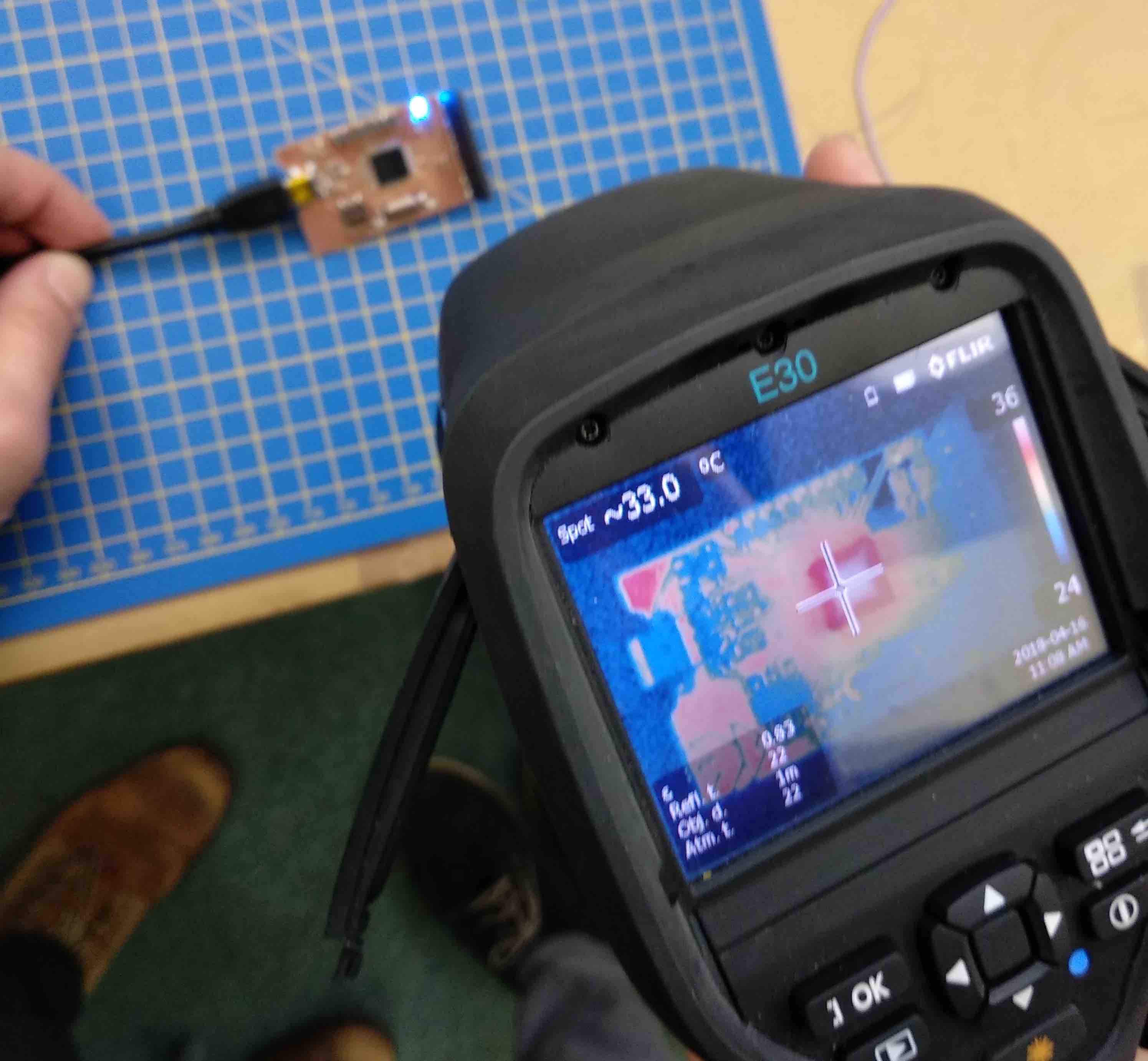
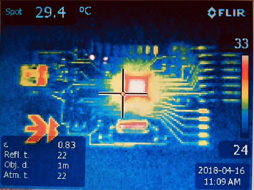
The microcontroller stabilizes at ~30 degrees C.
Programming the Bueno Board
Through ArduinoIDE:
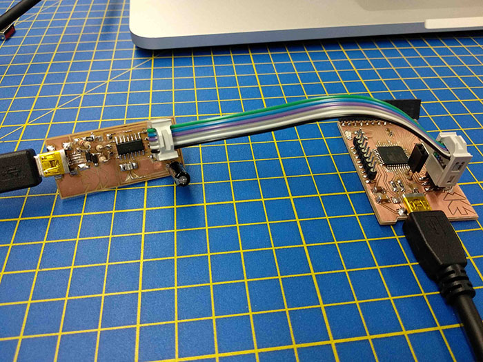
- Connect your programmer to your computer;
- Plug your Bueno Board to your Programmer;
- Power it (You can power it by plugging it to your computer, but not only. Power 5V to a VCC pin, and ground a GND pin, would also work);
- Open ArduinoIDE. I'm using version 1.8.5;
- On Tools > Board > Select "Arduino Leonardo";
- On Port > Have nothing selected;
- On Programmer > Select "USBtinyISP";
- Click on Burn Bootloader;
The Bootloader
The behaviour described above happens thanks to a special piece of code that is executed at every reset of the microcontroller and that looks for a sketch to be uploaded from the serial/USB port using a specific protocol and speed. If no connection is detected, the execution is passed to the code of your sketch.
This little (usually 512 bytes) piece of code is called the “Bootloader” and it is in an area of the memory of the microcontroller – at the end of the address space - that can’t be reprogrammed as a regular sketch and had been designed for such purpose.
To program the bootloader and provide to the microcontroller the compatibility with the Arduino Software (IDE) you need to use an In-circuit Serial Programmer (ISP) that is the device that connects to a specific set of pins of the microcontroller to perform the programming of the whole flash memory of the microcontroller, bootloader included. The ISP programming procedure also includes the writing of fuses: a special set of bits that define how the microcontroller works under specific circumstances.

This work is licensed under a Creative Commons Attribution-NonCommercial-ShareAlike 4.0 International License.