Bueno 3D - One:
-28/08/2018-
My first BIG 3D printer
I can be the type of person that when believes in one thing, talks about it.
I lost count on how many times I told people about my idea of building a big ass 3d printer to print fast and rought, quick and big.
My idea is that prints must not always look like it was not 3d printed. Maybe the contrary. Perhaps when it really looks like it was 3d printed, it can be a thing.
And foremost, THIS:
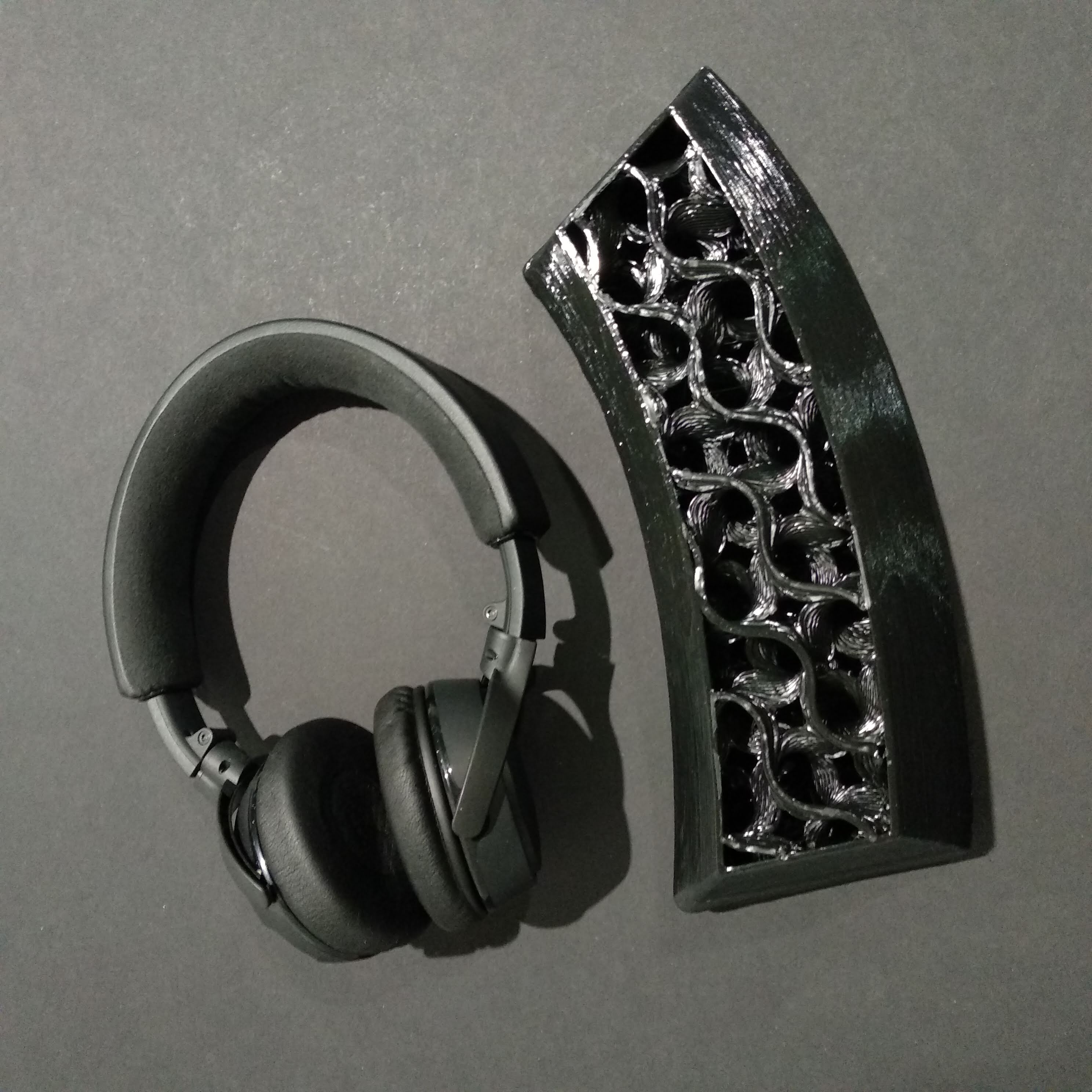
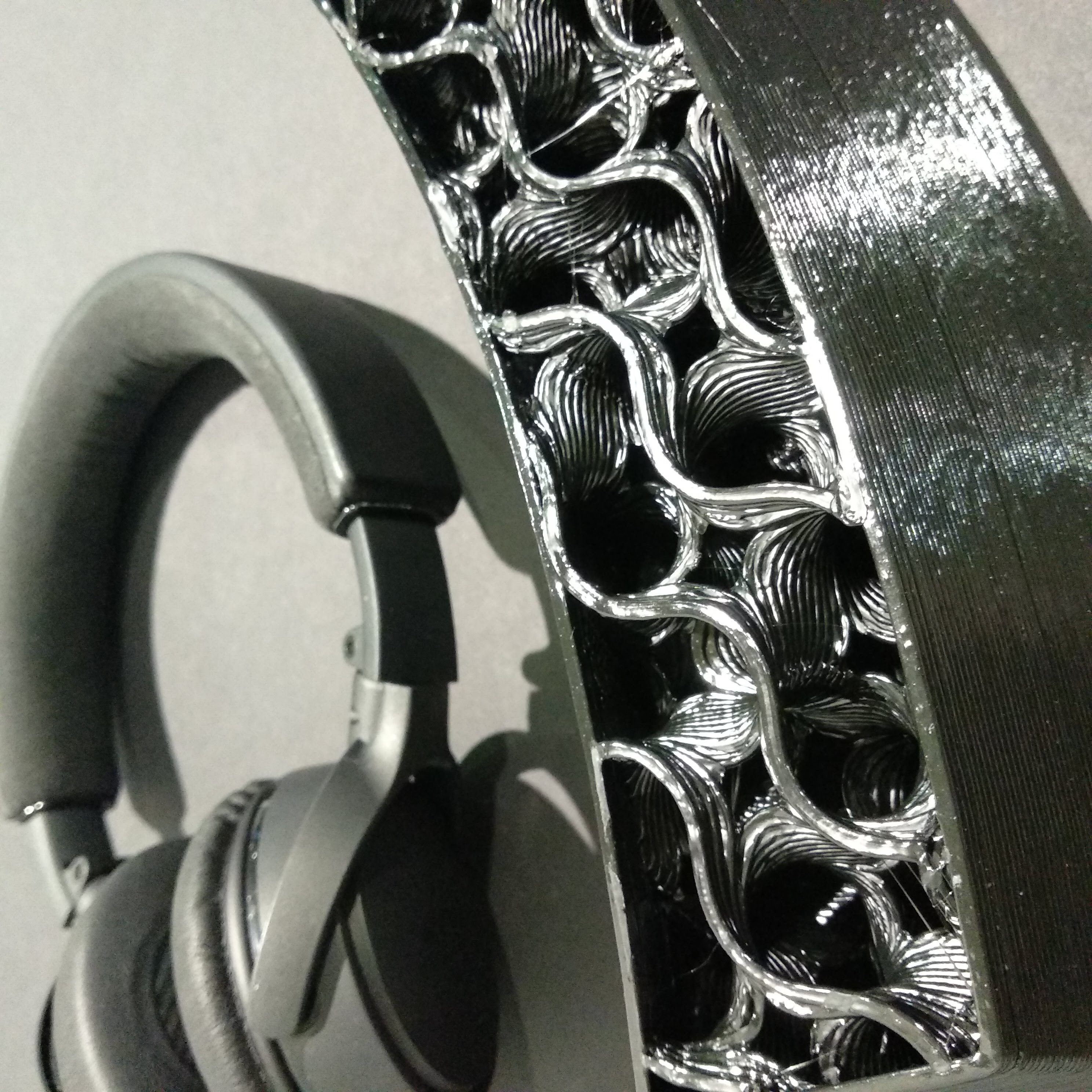
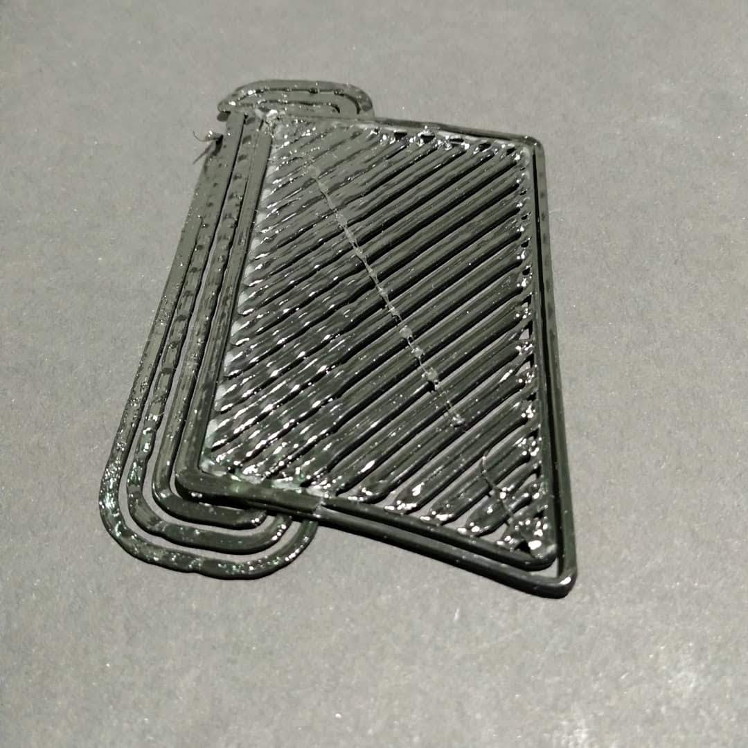
Here are some images of some of my latest prints:
Here is a video of my last print which gave me great results:
The printer started simple, like this:
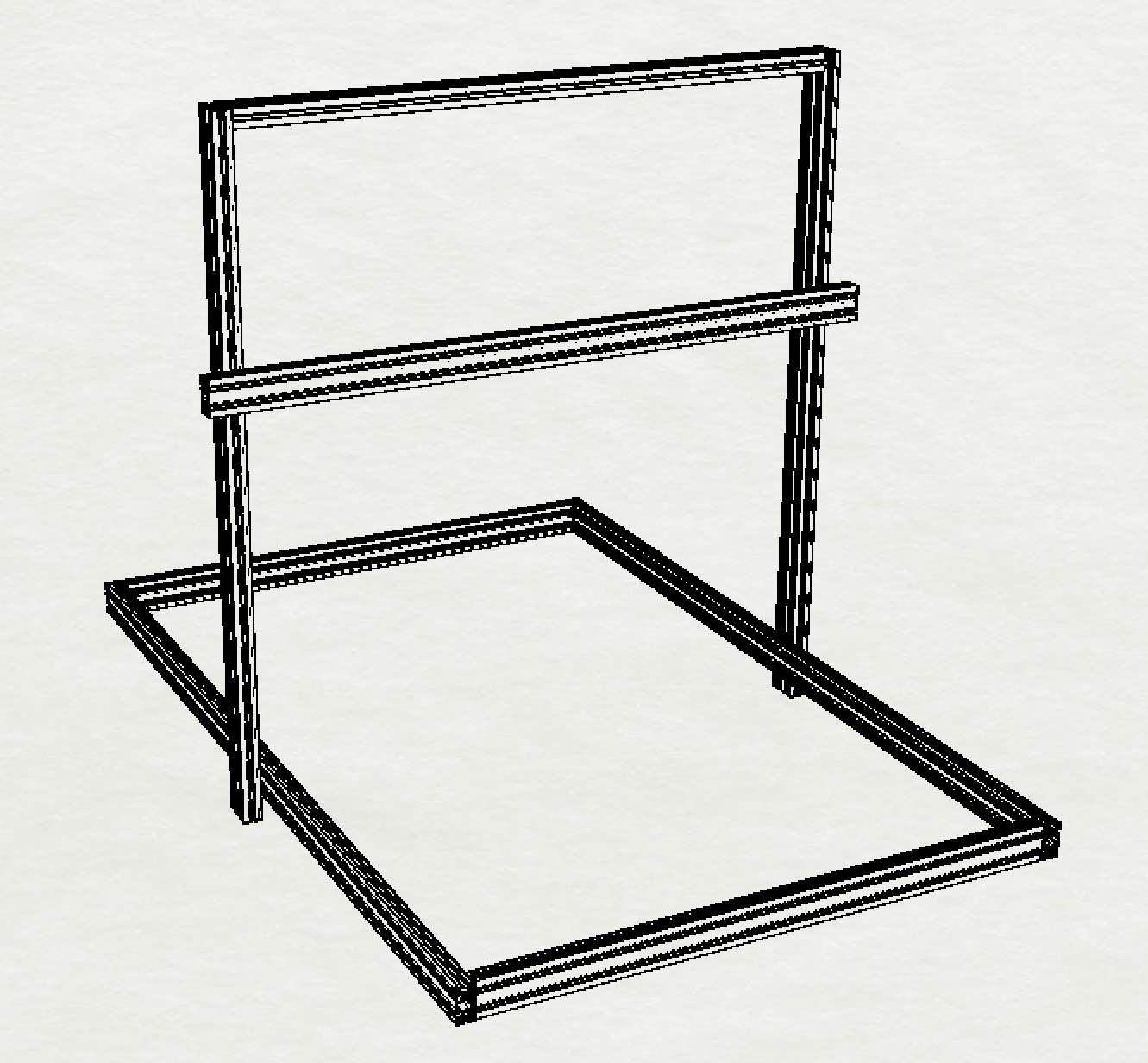
Without a reference, this could be any size. Adding dimensions: depth: 1600mm (1.6 meter) width: 1060mm (1 meter ~) Height: 1100mm (1.1 meter)
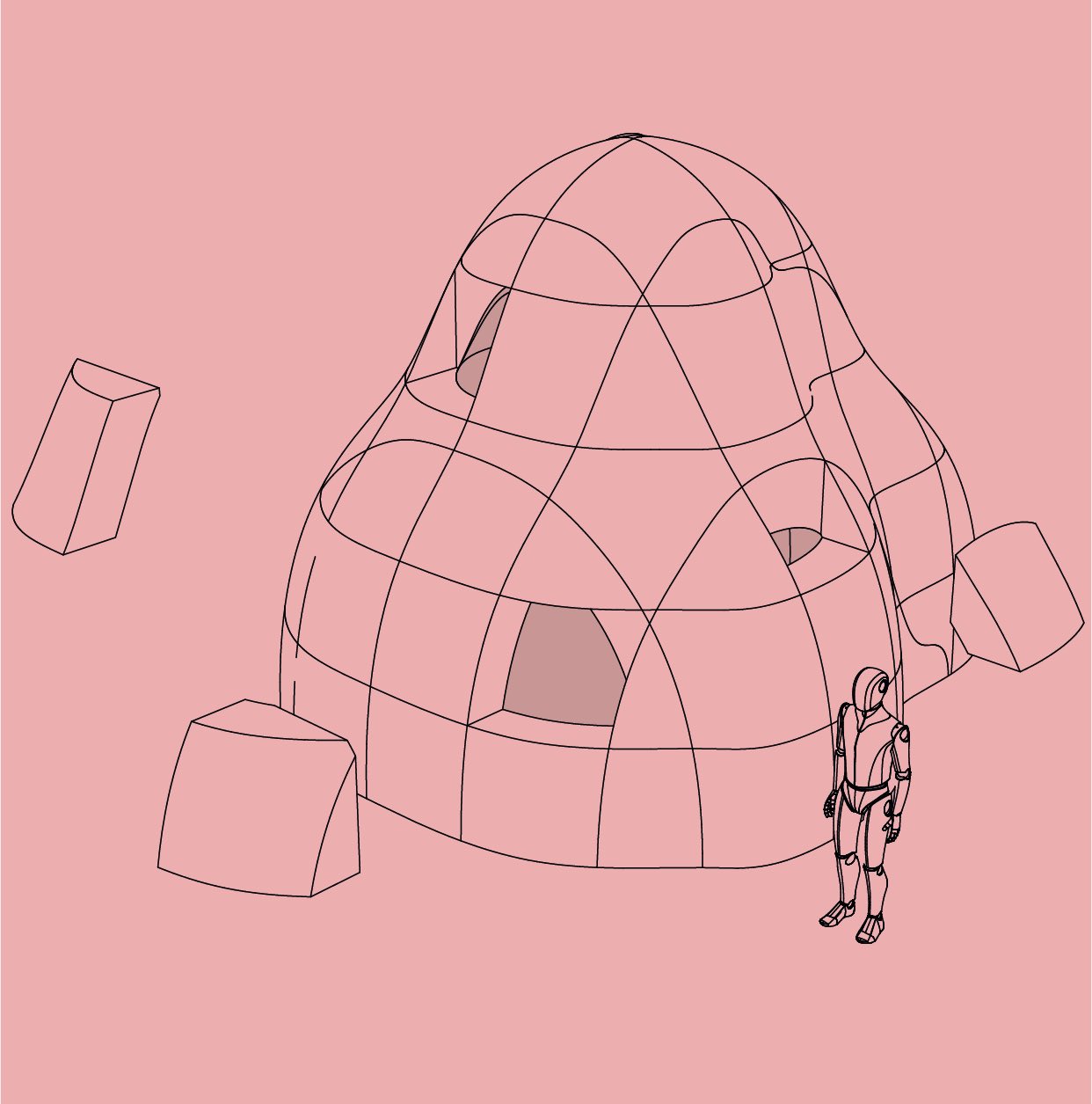
If it print a person-figure in the X-Y diagonal, It will be higher than many people I know.
But the intention was not to print people. Well, limitless actually.
ELECTRONICS of the printer:
the wiring of the nema23 with 8 wires was somehow simple. I had to solder the white-red to the white-blue, since blue and red are a coil. Same for the white-green white-black, soldered them together and in the stepper driver had them as another coil. But, since I had to invert the stepper motors to work inverted (since they’re in mirror position), The green wire of one stepper joined the black of the other and the black with the green. These mixed wires make a coil (A) and the Blue and the Red (B) were not mixed, straight red from one side with red from the other side, blue with blue, and these another coil (B as already mentioned). This YouTube tutorial did it. Thanks!
--This is the link to the data-sheet of the Nema23 above mentioned <- click
--And that's him <- click
I bought it on Amazon.co.uk, ~19.00 pounds.
The other nema23s I got came already with 4 wires. Easier to wire. Green and Black are a coil, Blue and Red another. Always check it. You can check it with a multimeter, Ohmmeter. The resistence will vary depending on the size of the coil and the gauge (AWG) of the copper wire used. In the data-sheet you'll find it.
The Diary:
I'm writing a diary of the printer. It is on paper. I like writing. I'll eventually post images of the pages. Not necessarily lazy but in fact because I like to show off when the calligraphy comes out clean ;)
https://reprap.org/wiki/RAMPS_1.4
OctoPi - OctoPrint
I'm using a Raspberry Pi to connect remotely to the printer. You go to this address and connect to your printer: http://octopi.local/
https://www.raspberrypi.org/forums/viewtopic.php?t=86253
Purchase:
-Tomorrow I'm driving to these guys to check out their metal sheet materials: Denmaysteel
-These guys were great, but the shipping would turn out to be the same price as the goods buymetalonline
-I'm looking at these guys to buy some Nylon: theplasticshop
I got a TITAN extruder from the guys of E3D: https://e3d-online.com/titan-extruder
This guys do recycling of PET into Filament in Spain: https://bpetfilament.com/
-
MARLIN
Configuration.h
229 - #define POWER_SUPPLY 0 // Later Include the PS_ON, it's the Emergency switch, I guess. 338 - // PID Tuning Guide here: http://reprap.org/wiki/PID_Tuning 475 - #define USE_ZMIN_PLUG // Turned this off for Z-Probe - Turned it back on due to error! 497 - #define Z_MIN_ENDSTOP_INVERTING true // set to true to invert the logic of the endstop. I had to turn it back to TRUE. False gave error! 501 - #define Z_MIN_PROBE_ENDSTOP_INVERTING false // set to true to invert the logic of the probe. -- I set to TRUE for Zprobe. Not sure. Set to False now*
611 - //#define Z_MIN_PROBE_ENDSTOP // Why is this commented?
631 - #define FIX_MOUNTED_PROBE // Inductive z sensor
688 - #define X_PROBE_OFFSET_FROM_EXTRUDER 47 // X offset: -left +right [of the nozzle] // Offset Zprobe
724 - #define Z_PROBE_OFFSET_RANGE_MIN -40 // was 20 725 - #define Z_PROBE_OFFSET_RANGE_MAX 40 // was -20
753 - #define INVERT_X_DIR true // Was false and Axis was going opposite direction of Endstop 754 - #define INVERT_Y_DIR true // SO WEIRD! Sometimes works one direction, then another. 755 - #define INVERT_Z_DIR false // Maybe this one to true also?
762 - // For direct drive extruder v9 set to true, for geared extruder set to false. 763 - #define INVERT_E0_DIR false // What's mine?
773 - //#define Z_HOMING_HEIGHT 4 // (in mm) Minimal z height before homing (G28) for Z clearance above the bed, clamps, ... // What does this do?
780 - #define Z_HOME_DIR -1 // This is the correct one for Z Probe 784 - #define X_BED_SIZE 900 785 - #define Y_BED_SIZE 1380 790 - #define Z_MIN_POS 0 // - WILL have to adjust this soon! This will trim Z up or down. 792 - #define Z_MAX_POS 920
805 - //#define MIN_SOFTWARE_ENDSTOPS // I Commented them out 813 - //#define MAX_SOFTWARE_ENDSTOPS // I Commented them out
873 - //#define AUTO_BED_LEVELING_3POINT // Still deciding which one is best* 875 - #define AUTO_BED_LEVELING_BILINEAR // Think im taking this one due to MESH
886 - #if ENABLED(MESH_BED_LEVELING) || ENABLED(AUTO_BED_LEVELING_BILINEAR) || ENABLED(AUTO_BED_LEVELING_UBL) // Gradually reduce leveling correction until a set height is reached, // at which point movement will be level to the machine's XY plane. // The height can be set with M420 Z (Smaller than)height(Bigger than)
901 - #define G26_MESH_VALIDATION // Enable G26 mesh validation 902 - #if ENABLED(G26_MESH_VALIDATION)
MESH: 913 - // Set the number of grid points per dimension. 914 - #define GRID_MAX_POINTS_X 5 915 - #define GRID_MAX_POINTS_Y 7 // was: GRID_MAX_POINTS_X
917 - // Set the boundaries for probing (where the probe can reach). 918 - #define LEFT_PROBE_BED_POSITION 65 // was 15 919 - #define RIGHT_PROBE_BED_POSITION 800 // was 170 920 - #define FRONT_PROBE_BED_POSITION 30 // was 20 921 - #define BACK_PROBE_BED_POSITION 1300 // was 170
923 - // The Z probe minimum outer margin (to validate G29 parameters). 924 - #define MIN_PROBE_EDGE 10 // Not sure really. Crosscheck. I guess 60mm. 939 - //#define ABL_BILINEAR_SUBDIVISION // To test in the future
1035 - #define Z_SAFE_HOMING
1038 - #define Z_SAFE_HOMING_X_POINT ((X_BED_SIZE) / 2) // X point for Z homing when homing all axes (G28) - I Dont understand these numbers! I'm trying to change it to ((X_BED_SIZE) * 0.8) For Y I'm also doing it. THis basically takes care that Z probe is not outside of the bed.
HINTS in Marlin:
JERK: 20% ~ the speed of your average print; If you're printing at 30mm/s, 6-10mm/s^2.
Acceleration:
Configuration-adv.h
831 - //#define MINIMUM_STEPPER_DIR_DELAY 650 // - try this for X step losses. 844 - //#define MINIMUM_STEPPER_PULSE 2 // try this as well for X step losses. 1361 - #define PINS_DEBUGGING // I uncommented it cause I couldnt move anything by starting PrintRun/Pronterface Then use the command M43 E1 to monitor them.
GCODES
I was researching about Absolute and Relative G-code commands ("G90" for Absolute and "G91" relative) and I've found this: https://www.simplify3d.com/support/articles/3d-printing-gcode-tutorial/
M43 E1 ; MOnitor pins - Endstops basically
M84 XY ; Disable X and Y steppers. Dont want to disable Z!
G92 E0 ;zero the extruded length
M119 - Tests the Endstops (Open or closed)
M106 S127 ; Fan On, Snn, S255 Max, S0 Min, S127 middle speed.
M107 ; Fan Off
M302 ; report current cold extrusion state
M302 P0 ; enable cold extrusion checking
M302 P1 ; disable cold extrusion checking
M302 S0 ; always allow extrusion (disable checking)
M302 S170 ; only allow extrusion above 170
M302 S170 P1 ; set min extrude temp to 170 but leave disabled
M303 E0 S200 C8 ; PID AUTO TEST
PROBLEMS:
10/September/2018 -Home all axis command sends Y to a different direction than Home Y. So weird! Line 754 of Configuration.h The problem was not that. Was the TBsomething stepper-driver of Y that was falty. I luckly had a second one and replacing it solved the problem.
-Z nema23 Driver is not strong enough for both stepper. Im not getting enough torque, they are missing steps.
-Delta Fan missing at the HotEnd (To cool the material fast for the next layer)
-Calibrate Z and E on Marlin. Z - 10mm software moves 12.5mm in the machine. The Steps per unit on Marlin are 70. E - to be measured.
Run a print test tomorrow.
Run also the PID test. M303 E0 S200 C8 ; Results of Auto PID tune:
PID Autotune start bias: 103 d: 103 min: 198.55 max: 202.86 bias: 97 d: 97 min: 198.26 max: 202.63 bias: 89 d: 89 min: 198.82 max: 202.23 Ku: 66.34 Tu: 21.46 Classic PID Kp: 39.80 Ki: 3.71 Kd: 106.79
--
c - #define DEFAULT_Kp 55.80 c - #define DEFAULT_Ki 6.03 c - #define DEFAULT_Kd 129.15
SOLUTOINS:
-Parallel heating elements It worked out greatly. The Current peak increased obviously to heat up but also the speed to reach the aim temp. I am using 2 heating elements with only one thermistor. For lack of time, I used 2 heating blocks (Alu) put together -PCB milling for wiring Drivers to Axis (4 wires, Gnd, Enable, Direction, Step) -PCB milling of end stop with 5k - 10k ohms. Both resistors work In the X i was having problems with interference so I used 5k ohms instead of 10k. The real problem was actually that the wires were wrapped together with the ones of the X axis stepper and that coused interference. Now analyse is the 5k is problematic in the future.

This work is licensed under a Creative Commons Attribution-NonCommercial-ShareAlike 4.0 International License.